USB-C, LiPo, 5V and 3.3V power modules
Small USB-C power modules are extremely useful for microcontroller projects. They can provide USB-C input power, charge a single-cell LiPo battery, boost battery voltage to 5V, regulate down to 3.3V, or combine several of these jobs on one board.
Contents
Basic module types
The term “USB-C LiPo module” can describe several different things. The most common types are listed below.
| Module type | What it does | Typical use | Watch out for |
|---|---|---|---|
| USB-C 5V input breakout | Only exposes USB-C 5V and GND, sometimes D+ / D- | Replacing a micro USB connector, powering a board from USB | No battery charging, no regulation beyond USB 5V |
| LiPo charger | Charges a 1S LiPo from USB | Battery-powered projects that do not need boost output | May not safely power the load while charging |
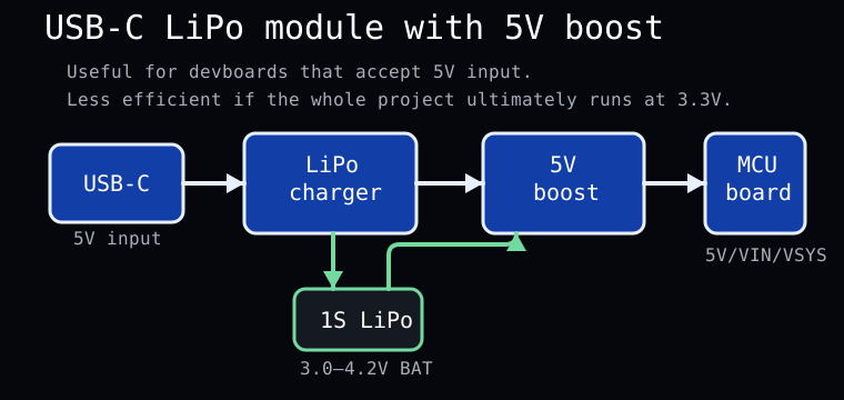
| LiPo charger + 5V boost | Charges 1S LiPo and boosts battery voltage to 5V | Small “powerbank style” MCU projects | Less efficient if the MCU ultimately runs at 3.3V |
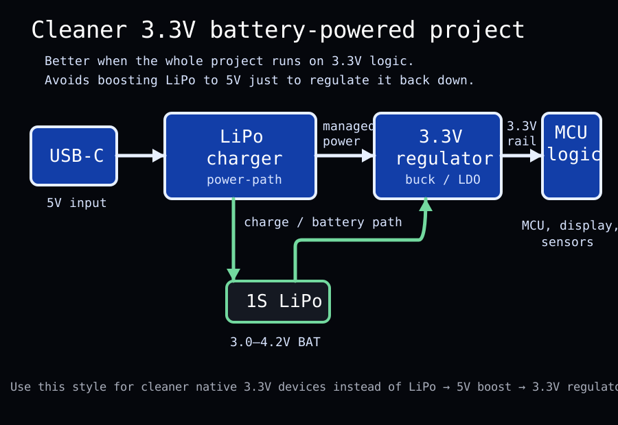
| LiPo charger + 3.3V regulator | Charges 1S LiPo and provides regulated 3.3V | ESP32, RP2040, sensors and low-power logic | Check maximum current carefully |
| Power-path LiPo module | Automatically manages USB input, battery charging and load power | More reliable portable devices | More expensive, but usually worth it |
USB-C input basics
A simple USB-C powered device normally receives 5V from the USB-C connector. For a USB-C charger or power supply to provide 5V correctly, the module should have the proper CC resistors on the USB-C connector.
For most microcontroller projects, plain USB-C 5V input is enough. USB Power Delivery trigger modules are a separate category and should only be used when the project really needs higher voltage.
Single-cell LiPo basics
Most small charger modules are intended for a single LiPo or Li-ion cell, often called 1S.
| State | Typical voltage |
|---|---|
| Fully charged 1S LiPo | 4.2V |
| Nominal voltage | 3.7V |
| Low battery region | around 3.0V–3.3V |
5V boost modules
A 5V boost module raises the battery voltage from roughly 3.0–4.2V up to a regulated 5V output. This is useful when the project expects USB-like 5V input.
Good uses for 5V output
- Arduino Nano style 5V boards
- Raspberry Pi Pico or similar boards through VSYS/VBUS-style inputs
- ESP32 dev boards through their 5V/VIN pin
- 5V sensors and LED modules
- projects where the board already has its own 3.3V regulator
3.3V regulator modules
Many modern microcontrollers and sensors run at 3.3V. In that case, a LiPo charger with a 3.3V buck or buck-boost output can be a cleaner solution than making 5V first.
Good uses for regulated 3.3V
- bare RP2040 designs
- ESP32 modules without a devboard regulator
- 3.3V OLED displays
- low-power sensors
- battery-powered devices where efficiency matters
Power-path and load sharing
A proper power-path circuit can power the project from USB when USB is connected, charge the battery at the same time, and switch to battery power when USB is removed.
Some cheap charger boards claim “charge and discharge at the same time”, but that does not always mean they have a proper power-path design. For simple hobby projects this may still work, but for a reliable device, real power-path / load sharing is better.
| Feature | Why it matters |
|---|---|
| Power-path / load sharing | Lets the device run from USB while charging the battery correctly |
| Battery protection | Helps prevent over-discharge, over-current and short-circuit problems |
| Enable pin | Allows the output regulator or boost converter to be switched off |
| Charge status pins or LEDs | Useful for front panels and debugging |
Common pin labels
Small modules often use short labels. The exact meaning depends on the board, but these are common interpretations.
| Label | Common meaning |
|---|---|
| VIN | Input voltage, often USB 5V or external 5V input |
| VU / VBUS | USB 5V directly from the USB connector |
| 5V | Regulated or boosted 5V output |
| 3V3 / 3.3V | Regulated 3.3V output |
| BAT | Raw battery voltage, usually 3.0–4.2V for 1S LiPo |
| G / GND | Ground |
| EN | Enable input for regulator or boost converter |
| D+ / D- | USB data lines, sometimes broken out for connection to a microcontroller |
Typical wiring examples
1. Simple 5V devboard project
2. Cleaner 3.3V battery-powered project
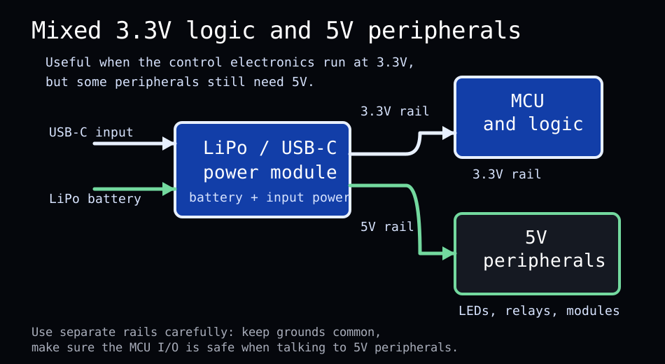
3. Mixed 3.3V logic and 5V peripherals
Useful modules to keep in stock
A small parts bin of power modules makes prototyping much faster.
| Module type | Why it is useful |
|---|---|
| USB-C 5V breakout | Quick way to add USB-C power input to a project |
| USB-C 1S LiPo charger | Basic battery charging for small devices |
| USB-C LiPo charger + 5V boost | Powerbank-style module for devboards and 5V projects |
| USB-C LiPo charger + 3.3V regulator | Cleaner solution for native 3.3V microcontroller projects |
| USB-C power-path charger module | Best choice for a proper portable device |
| Small 3.3V buck modules | Useful after a 5V module or higher-voltage input |
| USB-C PD trigger modules | Useful for 9V, 12V, 15V or 20V projects, but not needed for basic MCU power |
LiPo safety notes
- Use only chargers intended for the battery chemistry and cell count.
- Do not short the battery output.
- Do not charge damaged, swollen or unknown LiPo cells.
- Choose a charge current suitable for the battery capacity.
- Make sure the finished device cannot crush, puncture or overheat the cell.
- Use protected cells or modules with protection when possible.
Quick summary
- 5V boost modules are great for devboards and fast prototypes.
- 3.3V regulator modules are better for clean low-power MCU designs.
- Power-path modules are the best choice when the device should run while charging.
- BAT is usually raw LiPo voltage, not regulated output.
- VU/VBUS is usually USB 5V direct from the connector.
- Always measure before connecting expensive parts.
Last updated manually. Always check the datasheet or module schematic when available.